3. UML Overview
What is UML?
UML stands for "Unified Modeling Language".
UML is an international standard managed by the Object Management Group (OMG). UML has also been published by the International Organization for Standardization (ISO) and the International Electrotechnical Commission (IEC) as the ISO/IEC 19501 standard. (See ISO/IEC 19505-1:2012)
"The objective of UML is to provide system architects, software engineers, and software developers with tools for analysis, design, and implementation of software-based systems as well as for modeling business and similar processes."
In short, UML is a modeling language standard for describing systems and processes.
UML is often seen as only a description of diagramming conventions, or even just the rendered pixels of a UML diagram. While it certainly is that and primary focuses on the elements needed to create diagrams, it is much more than that. UML is a very precise and expansive description of all of the elements necessary to create, represent, store, and describe UML models in a general sense. What this means is that when you create a UML model and represent that model using the UML specification, you are open to do more than just render a diagram. For example, you may create your own custom notation, representations, or even diagrams. You may save your model in data stores. You may exchange models, transform them into other specifications, or generate documentation. Depending on the specificity of your model, you may even automatically generate code, libraries, SDKs, executables, or other artifacts. The possibilities are endless.
This course's main goal is to attempt to explain the diagramming aspect of UML Class Diagrams, but we hope to mix in other modeling capabilities of UML to become familiar with the many other aspects of modeling you may be interested in.
Diagram Types
There are many Diagram Types that you can create using UML.
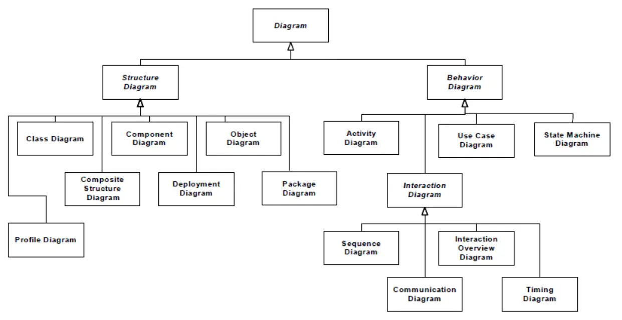
Generally they break down into 2 general types of diagrams: 1. Structure Diagrams and 2. Behavior Diagrams. Structure Diagrams generally focus on the structure of things and how they relate to each other. Behavior Diagrams generally focus on behaviors, how things change state, or process flows.
Although diagrams generally can be categorized into these two types, they can be mixed and combined to model both structure and behavior.
Purpose of Class Diagrams in UML
Class Diagrams fit within the "Structure Diagram" type of Diagrams. This means they primarily deal with the structure of a system and how those elements relate. This also means that they are generally not meant to model behavior, changes in state, or process flow. But there are aspects of Class Diagrams that can show relationships with things like "Operations" and "Behaviors" which are more behavioral in nature.
- Structure Diagrams
- Class Diagram
- Object Diagram
- Package Diagram
- Profile Diagram
- Composite Structure Diagram
- Component Diagram
- Deployment Diagram
- Behavior Diagrams
- Activity Diagram
- Use Case Diagram
- State Machine Diagram
- Interaction Diagram
- Sequence Diagram
- Communication Diagram
- Interaction Overview Diagram
- Timing Diagram
Class Diagrams are extremely useful for describing the structure of a system in terms of object-oriented principles (OOP). For example, consider the following elements that are part of UML Class Diagrams:
| UML elements | Similar concepts in OOP languages |
|---|---|
| Class | "class" |
| Interface | "interface" or "contract" |
| Package | "package" or "namespace" |
| Property | "property", "field, "attribute" |
| Operation | "method", "method signature, or "function" |
| Association | "references" |
| Generalization | "extends" or "inherits from" |
| InterfaceRealization | "implements" or "adheres to" |
As you can see, UML Class Diagrams are perfect for describing the structure of your application in OOP language that maps nicely to the programming langauges you are already familiar with.
It's probably no surprise that Class Diagrams are our favorite Diagram in the UML ecosystem. 😃
Why use UML Class Diagrams?
Anyone that wants to be successful in building anything must start with a solid architecture.
There are many software/application development processes and methodologies (See Software Development Process and Software Development Life Cycle for an example of a few), but every one of them begins with a "Plan" or "Design" phase before getting into the "Build" phase.
In other words, a successful project should be planned out and designed before being built. Would you start building a house without blueprints? Of course not. UML Class Diagrams are like your blueprints for your system and are crucial for the success of your project.
History of UML
UML has a long history. Here is a list of each of the officially released specifications:
| Version | Adoption Date | Time Between | Version Information | Specification URL(s) |
|---|---|---|---|---|
| 2.5.1 | December 2017 | 6 years, 5 months | https://www.omg.org/spec/UML/2.5.1 | |
| 2.4.1 | July 2011 | 1 years, 2 months | https://www.omg.org/spec/UML/2.4.1 | Infrastructure PDF Superstructure PDF |
| 2.3 | May 2010 | 1 years, 4 months | https://www.omg.org/spec/UML/2.3 | Infrastructure PDF Superstructure PDF |
| 2.2 | January 2009 | 1 years, 3 months | https://www.omg.org/spec/UML/2.2 | Infrastructure PDF Superstructure PDF |
| 2.1.2 | October 2007 | 2 years, 3 months | https://www.omg.org/spec/UML/2.1.2 | Infrastructure PDF Superstructure PDF |
| 2.0 | July 2005 | 2 years, 4 months | https://www.omg.org/spec/UML/2.0 | Infrastructure PDF Superstructure PDF |
| 1.5 | March 2003 | 1 years, 6 months | https://www.omg.org/spec/UML/1.5 | |
| 1.4 | September 2001 | 1 years, 7 months | https://www.omg.org/spec/UML/1.4 | |
| 1.3 | February 2000 | 7 months | https://www.omg.org/spec/UML/1.3 | |
| 1.2 | July 1999 | 1 year 7 months | https://www.omg.org/spec/UML/1.2 | |
| 1.1 | December 1997 | https://www.omg.org/spec/UML/1.1 |